
So considering this project is going to take so long, I have decided to post updates to this page as I progress. Let me first say, building a pinball machine has been in the back of my mind for a long time. However, I have been very hesitant to actually attempt to build one. I know it will take a while, I know it will be relatively expensive, and quite complex. There are many systems that go into one of these, both mechanical and electrical. I expect to learn many things from this project, and I suppose that's the real point anyway. Some things, right off the bat, I expect to learn doing this.
- The ins and outs of solenoids
- Driving a dot matrix display(Hardware & Software)
- Editing Audio
- How audio is actually stored and played
- Audio amplifiers
- Mixing multiple voltage supply's
- Using CAD to design printed circuit boards
- Object oriented programming
- Vacuum forming
- Creating vinyl artwork
- Protective Layering
- Wire forming
- Patience
After countless hours of playing pinball at the arcade and traversing the web looking at pinball hardware and 3rd party parts, I'm starting to get a better understanding of this whole pinball thing.
The first items I purchased were 3 pinballs, used bumper assemblies of various types, and several used targets and switches. I want to start this off with used, less expensive, parts just in case I change my mind about a part or break it in the process of learning all this.

While waiting for the parts to arrive, I designed two IO expansion modules for the micro controller. One 32 point Input module and one 32 point Output module. The input module consists of four 8bit parallel-in shift registers, and the output module consists of four 8bit parallel out shift registers. I designed a library for both expansions using an unsigned long variable for each then using an AND comparison to see the 32 points at the bit level. I have no better way of describing that right this second. If you are still interested, you can look at the code your self. In the video you can see a lot of bad flicker. this was due to me writing a function to see if output 0 was set to zero. If I remember correctly, a for loop was writing a zero into that register whenever it finished its loop. I have since wrote an independent function to turn all outputs off. No more flicker now.


I purchased this old pinball power supply from ebay. It was originally inside of an old pinball machine from the 70's. I thought getting this to work would be super simple. When it arrived and I sat down at my bench with it, I noticed it was a multi-tap transformer with many wires and no indication about which one was what. I couldn't find any documentation on the transformer online. I don't currently have an auto ranging multimeter and didn't want to go to the trouble of probing that big transformer every which way to figure out what was what. In a last ditch effort I searched the transformer part number again and matched it with the keyword "pinball". And bingo, I found out which pin this was originally from. It was from a 1977 Atari Airborne Avenger. One more googe search away and I found the owners manual to the game. There on page 68 was a seemingly hand drawn schematic of the power supply. This was a nicely documented game. I don't know if most machines were like this, but I will certainly strive to document my machine well enough that it can be repaired with relative ease. The drawing had wire colors and everything. I'm not sure if I'm actually going to use this old heavy linear supply or not. I know some people use switching power supplys that were designed for industrial applications, but if I run into no problems with this, then I think it's the way to go. Also, for the smaller voltages I will be using an ATX power supply to run the lights and logic.

Upon going through the drawing and figuring out what is still there I managed to label all the pinouts of the 3 front molex connectors. I purchased the mating molex connectors for the 3 just in case I might need them down the road.
Here's a quick demo of the pop bumpers in action. I do have brighter lights inside now but for some reason the newer video wouldn't upload. perhaps later. Also, I haven't yet figured out what exactly I'm going to do about the lights in the game. These games used to use 12v incandescent bulbs for all the various lights, but recently I have seen them getting replaced with LED bulbs of the same socket type. I purchased some of these 555 socket LED bulbs for the PirateCade cabinet but they seamed to burn out after about a month. I will have to buy several types and experiment to see what I should use for this.
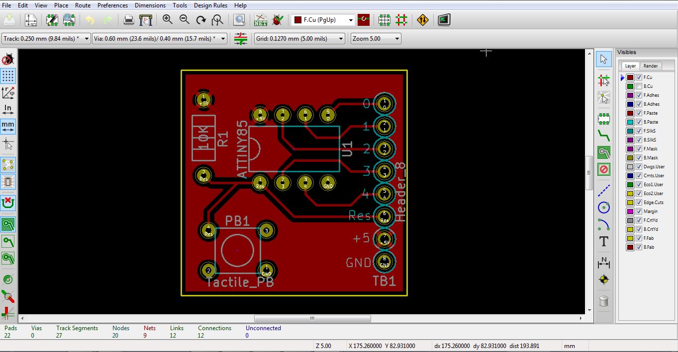
Oh Boy! I'm actually really excited about this one. I have been wanting to actually design a PCB and have it made for a long time. The thought of having to learn new software and screwing something up was just too daunting. But sometimes you just need to pull the trigger and just do it. Just like Shia Labeouf said. It took me no more than 6 hours to make myself comfortable in Kicad(PCB design software) making schematics, part footprints, and routing traces on the board. I actually really enjoyed it. I plotted the gerber files and sent them off to a board house to have my PCB manufactured. I am having it done through OSH Park. They will print pcb's at $5 per square inch of a 2 layered board, and they will send you 3 copies of your board. So, since my board is 1" x 1", my price for 3 boards was $5. Can't wait to see how it will turn out.

What is my circuit you ask? Well it's just a small ATtiny85 Breakout board with a built in reset switch. It has nothing to do with my pinball game but it was a $5 learning exercise to see if I actually have the hang of this whole thing. So even though this is just a small, almost pointless board, I am really excited about my new found skill and am even more motivated to design the rest of the hardware.
February 19, 2016
I was tinkering last night with my pop bumpers trying to get them to trigger better. I couldn't for the life of me get the switches positioned just right to where an even amount of pressure from all sides would activate the spoon switch. As I was adjusting and setting up the flipper assemblies, I thought the shaft of the flipper looked too low. I got out my calipers and discovered the distance between the bottom of the flipper and the top of the mounting bracket was just over 1/2". This tells me that the playfield this flipper came from was 1/2" thick. The board I have been testing the bumpers with is 3/4". After a quick search I learned the standard thickness of a playfield is indeed 1/2". I will have to set up my bumpers on a 1/2" board to see what difference it will make. My guess is a lot.
Here's the new video of the lights in the bumpers.
No comments:
Post a Comment